

Photo Record
Images
![Fulp [Bridge Keeper's] House, see detailed caption #558 (2010)](https://s3.amazonaws.com/pastperfectonline/images/museum_296/004/thumbs/100501061-4.jpg)
![Fulp [Bridge Keeper's] House, see detailed caption #533 (2010)](https://s3.amazonaws.com/pastperfectonline/images/museum_296/004/thumbs/100501061-5.jpg)
![Fulp [Bridge Keeper's] House, see detailed caption #519 (2010)](https://s3.amazonaws.com/pastperfectonline/images/museum_296/004/thumbs/100501061-6.jpg)
Additional Images [42]
![Fulp [Bridge Keeper's] House, see detailed caption #540 (2010)](https://s3.amazonaws.com/pastperfectonline/images/museum_296/004/thumbs/100501061-7.jpg)
![Fulp [Bridge Keeper's] House, see detailed caption #543 (2010)](https://s3.amazonaws.com/pastperfectonline/images/museum_296/004/thumbs/100501061-8.jpg)
![Fulp [Bridge Keeper's] House, see detailed caption #501 (2010)](https://s3.amazonaws.com/pastperfectonline/images/museum_296/004/thumbs/100501061-9.jpg)
![Fulp [Bridge Keeper's] House, see detailed caption #622 (2010)](https://s3.amazonaws.com/pastperfectonline/images/museum_296/004/thumbs/100501061-10.jpg)
![Fulp [Bridge Keeper's] House, see detailed caption #361 (2010)](https://s3.amazonaws.com/pastperfectonline/images/museum_296/004/thumbs/100501061-11.jpg)
![Fulp [Bridge Keeper's] House, see detailed caption #1168 (2010)](https://s3.amazonaws.com/pastperfectonline/images/museum_296/004/thumbs/100501061-12.jpg)
![Fulp [Bridge Keeper's] House, see detailed caption #41 (2010)](https://s3.amazonaws.com/pastperfectonline/images/museum_296/004/thumbs/100501061-13.jpg)
![Fulp [Bridge Keeper's] House, see detailed caption #382 (2010)](https://s3.amazonaws.com/pastperfectonline/images/museum_296/004/thumbs/100501061-14.jpg)
![Fulp [Bridge Keeper's] House, see detailed caption #385 (2010)](https://s3.amazonaws.com/pastperfectonline/images/museum_296/004/thumbs/100501061-15.jpg)
![Fulp [Bridge Keeper's] House, see detailed caption #386 (2010)](https://s3.amazonaws.com/pastperfectonline/images/museum_296/004/thumbs/100501061-16.jpg)
![Fulp [Bridge Keeper's] House, see detailed caption #389 (2010)](https://s3.amazonaws.com/pastperfectonline/images/museum_296/004/thumbs/100501061-17.jpg)
![Fulp [Bridge Keeper's] House, see detailed caption #410 (2010)](https://s3.amazonaws.com/pastperfectonline/images/museum_296/004/thumbs/100501061-18.jpg)
![Fulp [Bridge Keeper's] House, see detailed caption #435 (2010)](https://s3.amazonaws.com/pastperfectonline/images/museum_296/004/thumbs/100501061-19.jpg)
![Fulp [Bridge Keeper's] House, see detailed caption #503 (2010)](https://s3.amazonaws.com/pastperfectonline/images/museum_296/004/thumbs/100501061-20.jpg)
![Fulp [Bridge Keeper's] House, see detailed caption #505 (2010)](https://s3.amazonaws.com/pastperfectonline/images/museum_296/004/thumbs/100501061-21.jpg)
![Fulp [Bridge Keeper's] House, see detailed caption #1197 (2010)](https://s3.amazonaws.com/pastperfectonline/images/museum_296/004/thumbs/100501061-22.jpg)
![Fulp [Bridge Keeper's] House, see detailed caption #980 (2010)](https://s3.amazonaws.com/pastperfectonline/images/museum_296/004/thumbs/100501061-23.jpg)
![Fulp [Bridge Keeper's] House, see detailed caption #1429 (2010)](https://s3.amazonaws.com/pastperfectonline/images/museum_296/004/thumbs/100501061-24.jpg)
![Fulp [Bridge Keeper's] House, see detailed caption #1008 (2010)](https://s3.amazonaws.com/pastperfectonline/images/museum_296/004/thumbs/100501061-25.jpg)
![Fulp [Bridge Keeper's] House, see detailed caption #935 (2010)](https://s3.amazonaws.com/pastperfectonline/images/museum_296/004/thumbs/100501061-26.jpg)
![Fulp [Bridge Keeper's] House, see detailed caption #936 (2010)](https://s3.amazonaws.com/pastperfectonline/images/museum_296/004/thumbs/100501061-27.jpg)
![Fulp [Bridge Keeper's] House, see detailed caption #982 (2010)](https://s3.amazonaws.com/pastperfectonline/images/museum_296/004/thumbs/100501061-28.jpg)
![Fulp [Bridge Keeper's] House, see detailed caption #501 (2010)](https://s3.amazonaws.com/pastperfectonline/images/museum_296/004/thumbs/100501061-29.jpg)
![Fulp [Bridge Keeper's] House, see detailed caption #502 (2010)](https://s3.amazonaws.com/pastperfectonline/images/museum_296/004/thumbs/100501061-30.jpg)
![Fulp [Bridge Keeper's] House, see detailed caption #582 (2010)](https://s3.amazonaws.com/pastperfectonline/images/museum_296/004/thumbs/100501061-31.jpg)
![Fulp [Bridge Keeper's] House, see detailed caption #619 (2010)](https://s3.amazonaws.com/pastperfectonline/images/museum_296/004/thumbs/100501061-32.jpg)
![Fulp [Bridge Keeper's] House, see detailed caption #624 (2010)](https://s3.amazonaws.com/pastperfectonline/images/museum_296/004/thumbs/100501061-33.jpg)
![Fulp [Bridge Keeper's] House, see detailed caption #1398 (2010)](https://s3.amazonaws.com/pastperfectonline/images/museum_296/004/thumbs/100501061-34.jpg)
![Fulp [Bridge Keeper's] House, see detailed caption #1403 (2010)](https://s3.amazonaws.com/pastperfectonline/images/museum_296/004/thumbs/100501061-35.jpg)
![Fulp [Bridge Keeper's] House, see detailed caption #1404 (2010)](https://s3.amazonaws.com/pastperfectonline/images/museum_296/004/thumbs/100501061-36.jpg)
![Fulp [Bridge Keeper's] House, see detailed caption #1409 (2010)](https://s3.amazonaws.com/pastperfectonline/images/museum_296/004/thumbs/100501061-37.jpg)
![Fulp [Bridge Keeper's] House, see detailed caption #1411 (2010)](https://s3.amazonaws.com/pastperfectonline/images/museum_296/004/thumbs/100501061-38.jpg)
![Fulp [Bridge Keeper's] House, see detailed caption #1399 (2010)](https://s3.amazonaws.com/pastperfectonline/images/museum_296/004/thumbs/100501061-39.jpg)
![Fulp [Bridge Keeper's] House, see detailed caption #1613 (2010)](https://s3.amazonaws.com/pastperfectonline/images/museum_296/004/thumbs/100501061-40.jpg)
![Fulp [Bridge Keeper's] House, see detailed caption #1615 (2010)](https://s3.amazonaws.com/pastperfectonline/images/museum_296/004/thumbs/100501061-41.jpg)
![Fulp [Bridge Keeper's] House, see detailed caption #1616 (2010)](https://s3.amazonaws.com/pastperfectonline/images/museum_296/004/thumbs/100501061-42.jpg)
![Fulp [Bridge Keeper's] House, see detailed caption #1617 (2010)](https://s3.amazonaws.com/pastperfectonline/images/museum_296/004/thumbs/100501061-43.jpg)
![Fulp [Bridge Keeper's] House, see detailed caption #1618 (2010)](https://s3.amazonaws.com/pastperfectonline/images/museum_296/004/thumbs/100501061-44.jpg)
![Fulp [Bridge Keeper's] House, see detailed caption #1619 (2010)](https://s3.amazonaws.com/pastperfectonline/images/museum_296/004/thumbs/100501061-45.jpg)
![Fulp [Bridge Keeper's] House, see detailed caption #1620 (2010)](https://s3.amazonaws.com/pastperfectonline/images/museum_296/004/thumbs/100501061-46.jpg)
![Fulp [Bridge Keeper's] House, see detailed caption #1621 (2010)](https://s3.amazonaws.com/pastperfectonline/images/museum_296/004/thumbs/100501061-47.jpg)
![Fulp [Bridge Keeper's] House, see detailed caption #1622 (2010)](https://s3.amazonaws.com/pastperfectonline/images/museum_296/004/thumbs/100501061-48.jpg)
Metadata
Collection |
Michael Fulp House |
Title |
Stabilization of fireplace lintel and related stonework (2010), 48 photographs |
Archive Number |
MFHPH57 |
Description |
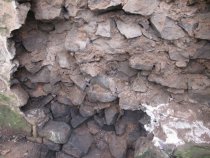
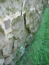
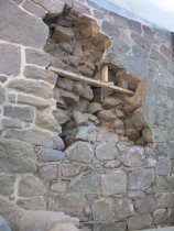
Series of 48 digital photographs showing the stabilization measures performed on the Fulp (formerly the "Bridge Keeper's") House fireplace lintel and associated stonework. The masonry supporting the oak fireplace lintel{1} in the east eaves wall had become compromised by the widespread disintegration of mortar in the wall core [see Image #408, 10/27/10]. After continual moisture infiltration and destructive freeze-thaw cycles, the dry and fragmented mortar residue had lost its capacity to resist movement of individual stones ["units"] in the wall. Fractures and a swelling "bulge were evident from the exterior when the wall was viewed at a raking angle.. These defects were compounded by the de-lamination of the exterior wythe of this masonry range from the core of the wall [see Image #605, 5/30/09, for a view after reconstruction, prior to re-pointing; see Image #576, 11/3/10 ]. As these dislocations occurred, the sill ["pad-stone"] under the end-block of the lintel was no longer in a mechanically centered support position. The lintel had rotated a few degrees clockwise and had deflected slightly. The de-stabilized condition was evident from the fractured wall segment under the pad-stone [see photo #605], cracks in the interior plaster finish and in the mortar joints north of the lintel, and the separation between the dislodged eastern end of the lintel and the masonry it was intended to support. The risk of catastrophic failure in these circumstances was quite high, threatening the stability of the massive chimney breast carried across the fireplace opening by the lintel. These interdependent structural components remained marginally stable partly because of the cantilever{2} function performed by the lintel, which was clamped onto the western pier [" jamb"] of the fireplace, in marginal compression on two small oak bearing plates{3}. This mechanical assist, together with the 20th-century hard plaster coating on the interior of the wall, cumulatively relieved a portion of the load on the bearing-masonry at the eastern end of the lintel, possibly averting a critical failure. The vertical deflection of the lintel across the fireplace opening was nearly 1 inch, roughly corresponding to the separation of the lintel from the stonework above it in the east wall. In addition, the white oak lintel has deformed slightly along a catenary curve, increasing the tension in its lower range. If the 12-inch dimension of the lintel had been placed on the vertical axis rather than the 10.5-inch dimension [a 14% change], its beam-strength would have been more than 25% greater because the vertical dimension of a beam is squared in calculating its load-bearing capacity. REMEDIATION of structural deficiencies and threats included the following materials, strategies, and methods: (a) reconstructing the unstable core and exterior stonework of the east eaves wall, including re-centering the sill [see Image #558, 11/3/10] and supporting it on a re-stabilized wall core; (b) fully packing all voids and joints in the masonry supporting the lintel with mortar and small stones ["pins" and "plugs"] increasing the ratio of stone-to-mortar in the restored walling and reducing the volume of space in the wall occupied only by mortar or its ineffective "rubble" residue; (c) installing solidly bedded "bond stones" as ties across mortar joints in the wall core; (d) treating accessible lintel surfaces and end-grain with the fluid depicted in Image #533{4}. Photos #519, 540 & 543 show the darkened lintel after spraying with this preservative. (e) The lintel was supported on temporary posts ["dead shores"] set on the hearth of the fireplace during the reconstruction of the southern bay of the wall in which the end-block of the lintel is embedded and borne. (f) setting relatively longer stones "toothed" into contiguous wall segments [see #1197, 1/22/10, #980, 11/17/10, #1429, 11/26/10, and #1008, 11/18/10, showing such "bond" stones protruding from the chimney into the plane of the gable masonry]; (g) applying precisely formulated mortar mixes to produce the optimum balance of resilience and strength [see record BKR10PH4--1005.01.060 for discussion of the suitable mortars for this restoration project]. (h) Corrugated metal ties [Photos #935 & #936, 11/14/10] were selectively deployed to mechanically connect adjacent wall segments, in this instance the structural junction of the sloping(a) chimney stack and south gable wall. Photos #980 & #982, 11/17/10, show two such ties set in the bed joint above the concrete lintel embedded in the upper chimney. These crimped metal strips were integrated into mortared bed joints as a redundant element supplementing the primary "tie" function of the bond-stones. (a) "corbelled"; also, "gathered," in the British vernacular. DETAILED CAPTIONS #361, 10/4/10: Fireplace with lintel shored on a small beam set on wooden posts during restoration of the east eaves wall. The posts to the left are the shoring timbers installed to help support the 2nd floor loads during restoration of the wall, the fireplace lintel, and its support system. #1168, 10/08/10: short posts in crawl space supporting loads transmitted through shoring posts ["dead shores", seen supporting floor joists in #361] on the first floor. #41, 10/19/10: Perspective view showing cracks in plaster and stonework adjacent to entry plane of lintel at the wall face. Photo #42 shows the full lintel and the bearing plates ["pads"] in the masonry pier ["jamb"] to the right [west]. #382, 10/26/10: Mason removing stones and mortar residue{b} from exterior wythe and core of wall, exposing end-grain of lintel and askew pad-stone supporting it. {b} This material was a dry mixture of clay, sand, and local soils and was easily raked or swept from the core of the wall, demonstrating its ineffectiveness as a bonding material. #385, #386, #389: Marginally deteriorated end-grain of lintel and surrounding masonry. Disintegrated mortar residue is apparent in bed joints under stones. Vacant space above lintel shows lack of bearing contact between lintel and masonry mass it was intended to carry. Pad-stone is off center under lintel, not an efficient bearing position and not anchored position adequately to inhibit displacement of the lintel and supporting masonry. A mechanically efficient bearing structure for the lintel requires that the pad-stone ["sill"] must be aligned on both primary axes and be supported in stable compression within the wall. #410, 10/28/10: Lintel positioned rotated off-center on pad-stone and slightly deflected from the horizontal axis. These dislocations impaired the function of the lintel as a major support beam, resulting in an unstable condition in the east wall and the chimney enclosure in the eastern bay of the south gable wall. This structural threat was compounded by the deteriorated and dehydrated mortar residue visible in the masonry joints below the pad-stone. This material, essentially a coarse gravel no longer capable of absorbing or attenuating stresses in the wall, provided minimal "padding" value to the wall structure. Well formulated and fully distributed mortar serves as a stabilizing shock-absorber, counteracting stresses and neutralizing strains in the wall. #435: Perspective view of eastern end-grain of lintel, with close view of erosion to wood fiber from interaction with lime and moisture in the wall core. #503 & 505: Lintel supported on shoring posts after removal of the bearing masonry. #503 [left half of the photo] also reveals the minimal use of bond stones in the original construction, which would have mechanically connected the inner and outer segments ["wythes"] of the wall. Lacking effective masonry "ties" and functioning mortar, the chimney had separated from the gable wall to a threatening degree, and the wall had developed long radiating cracks through contiguous mortar beds and joints. #501: Under-view of lintel showing its end-block and the wide chamfer, which is designed to attenuate any turbulence in the heated up-draft, thus reducing back-flow into the living space. The dark triangle slightly below the center of the photo is the inside of the western end-block of the lintel. Saw cuts at the ends of the chamfer indicate that it was "cut-from-the-solid" of a hewn beam, not pieced or fitted from several dimensioned timbers ["scantling"]. The lighter wood on which the western end-block rests is one of the two bearing plates extending southward into the fireplace jamb. #502, 11/02/10: Detail of east end of lintel, exposing the substantial voids and vacant joints in the masonry borne by the lintel. It is evident that this disintegrated wall segment lacked the requisite level bearing contact between the beam and the masonry mass it is intended to carry. These open joints will be tightly packed with mortar and small stones ["pins" (of small diameters and roughly cylindrical) and "plugs" (other shapes and sizes)](c) to inhibit dislocation of the constituent stone units of the wall. This restoration and reinforcement technique establishes a functionally stable and virtually monolithic wall system. The foundation walls under the entire structure have been substantially strengthened by this painstaking method, a traditional technique within the "art and mystery" of the mason's craft. Unlike gable-end walls, the eaves wall is a critical bearing structure for the roof and masonry loads and must be maintained "in compression", by means of collar ties and [nominally] plate-ties, to absorb and counterbalance the gravitational loads and oblique thrust acting on it. (c) These inserted stones were carefully selected for size and shape, and were tapped into the bed mortar with the mason's hammer. #576, 11/3/10: Top of the lintel is visible above the restored bearing wall. The gray material in the voids between stones is the mortar in-fill. Over twenty tons of carefully formulated mortar{d} were added to the structural mass of the building during the structure-wide restoration campaign, of substantially greater mass, bearing, and bonding quality than the disintegrated residue removed from the walls during dismantling. {d} The parameters considered to be appropriate for the stonework in this building are in the range of 2 to 3 parts aggregate [sand] to 1 part combined binders [lime and Portland cement]. Two formulas have been applied, the first stronger [higher in binders] than the second: 1) 5 parts yellow bar sand, 2 parts white lime, 1 part gray Portland cement; this mix was used mostly in the sub-grade foundation work and the core of the wall, where the "finish" details of color, texture, and the granulation variety of the aggregate are less significant than the stabilizing quality of the mortar; 2) 4 parts #2 sand ["Jersey Buff"], 2 parts #4 sand ["White Mason's Sand"], 2 parts white lime, 1 part gray Portland cement; this formula was used in the south gable wall and for pointing mortar in other above-grade repaired wall segments. Color, aggregate "speckling", and texture of the exposed pointing will be controlled by removing the lime haze ["milk"] from the mortar joints by the most effective and least invasive means available. #582: Back-pointing of interior wythe and fully mortared beds, joints, and voids adjacent to bearing site of lintel in the core of the wall. This mortar in-fill affords substantial stability to the wall by preventing movement of individual stone "units" by forces acting within the wall. The two-by-four "bridging" shore, mechanically a beam borne by posts, is designed to support the cantilevered stones at the margins of the temporary cavity in the wall range undergoing restoration. #619, 11/5/10: The eastern end-block and beveled underside ["smoke-baffle"] of the lintel. #622- The western end-block and face-slab of the lintel borne on the two bearing [and leveling] oak plates embedded in the masonry pier ["jamb", "leg"] of the fireplace. #624: Detail of lintel's west end-block and chamfer from inside the fireplace. #1398, 11/26/10: Chamfered lintel, supported on shoring posts and beam, viewed through the fireplace from outside the partially removed south gable wall. ##1403 & 1404: East and west segments of lintel showing exposed lower triangle of rectangular end-blocks; 1404 also shows one of the two lintel bearing-plates in the western pier ["jamb"] of the fireplace. #1409, 11/26/10: Detail of eastern end-block and charred upper portion of lintel. #1411: Detail of western end-block and bearing plate. #1399, 11/26/10 & #1176, 11/22/10: Detail views up the chimney and from outside the gable wall. The two iron bars projecting across the chimney flue{e}, approximately 7 feet above the hearth and embedded in mortar joints in each structure, would appear to function as ties between the chimney breast and the gable masonry. However, it is more likely that they are supports for "lug-poles" from which cooking pots and kettles were suspended on hangers or chains{f}. {e} the "funnel" of the chimney "shaft" in the British lexicon up to the mid-19th century. {f} See essay on "Fireplace and Chimney" in "The Pennsylvania German Family Farm" by Amos Long, Jr., Pennsylvania German Society (1972), p. 96 et seq. #1613, 12/4/10" View up chimney from hearth showing refractory mortar applied to interior of the three standing chimney wythes. #1615 through #1622 is a series of detail photos of the lintel's hewn [as indicted by "facets"] chamfer, and the inner faces of its end-blocks. The nails protruding from the lintel from various periods are probably hooks for hanging cooking vessels over the fire or embers [see Long, A., op. cit. in note {f} to #1399 above, p. 96]. FOOTNOTES {1} also called a "chimney-tree," "manteltree," "chimney girt," and "balk" [Long, op cit. in footnote {f} under #1399 above], all referring to the large beam spanning the fireplace opening and supported by the masonry pier ["jamb" or "leg"] to the west and by the east eaves wall masonry in which it is embedded. This lintel, 12 inches horizontally x 10.5 inches vertically{g}, carries a substantial portion of the loads imposed by the masonry chimney "breast" and the "stack" [also "pile"] rising, partially corbelled, through the roof. The exposed length of the lintel is 92 inches. The two bearing plates ["pads"] supporting the west end of the lintel are 2.5 x 9 inches. (g) The length of the exposed face of the lintel is 92 inches. The interior chamfer is 65 inches long and 10 inches across its diagonal surface. The mechanical [bearing] strength of a beam is proportionate to the square of its vertical dimension, but only to the numeric value of its horizontal measure. The vertical dimension is thus the more critical by an exponential factor. The bearing capacity of a chamfered lintel is further reduced by the loss of the triangular timber cut off along the chamfer between end-blocks. However, the tensile strength of white oak is extremely high in proportion to its dimensions, compensating for the reduction in the volume of timber performing the bearing function in this common form of "chimney tree." For further discussion of the function, sizing, and performance of beams, see DTR09PH138--1001.01.244. {2} A projecting horizontal structural member supported solely or partially at one end and projecting over a fulcrum at the margin of the bearing structure. {3} These short embedded timbers are 2.5 x 9 inches and penetrate approximately 24 inches southward into the pier. See photo #501, 11/2/10 and #622, 11/5/10. {4} According to the manufacturer's label [see photo#533, 10/2/10], this "Penetrating Fungicide, Termiticide and Preservative…Prevents Wood Decay…Fungi (Wet and Dry Rot), Termites, Carpenter Ants, Wood Boring Beetles." Larry Ward |
Search Terms |
MFHPH MFH Michael Fulp House MFR10PH Fireplace Lintel Mantel Tree Chimney Tree Chimney Girt Balk Fireplace Jamb Wood Preservative Pad Stone Shoring Post Bond Stone Metal Tie Mortar Mix Back-pointing Smoke Baffle Lintel Chamfer Chamfered Lintel Beam Mechanics |
People |
Michael Fulp |
Object Name |
Print, Photographic |
Accession number |
1005.01 |
Date |
10/04/2010 thru 12/04/2010 |
Photographer |
Ward, Laurence |
Catalog Number |
1005.01.061 |