

Photo Record
Images
Additional Images [17]
Metadata
Collection |
Michael Fulp House |
Title |
Interior foundation wall restoration |
Archive Number |
MFHPH54 |
Description |
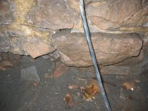
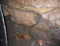
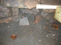
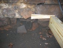
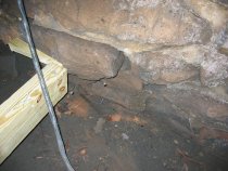
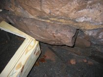
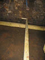
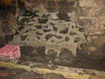
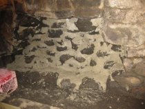
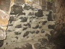
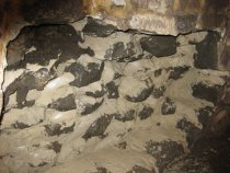
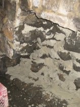
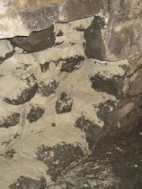
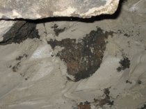
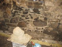
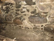
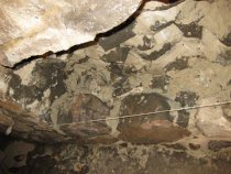
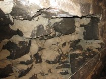
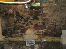
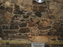
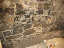
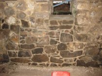
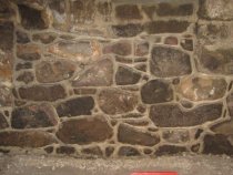
A series of 23 digital photographs showing restoration of the displaced and unstable central segment of the east cellar wall foundation. This wall had been severely destabilized and displaced [several inches into the cellar] by long term saturation of the bed and pointing mortar. Eventually persistent hydrostatic pressure from ground water, augmented by periodic river flooding and probably caused by "perched"{1} water in the soil, laterally pushed wall stones inward, sometimes rotating them in the process. Concave displacement of the exterior wythe of the wall corresponds on an axis through the wall with the location of the stones intruding into the cellar [see MFR10PH3--1005.01.059]. DETAILED CAPTIONS #580 & #581, 5/25/09 & #614, 6/03/09: Dislodged wall stones thrust into the cellar by hydrostatic pressure in saturated soils. Water and the darkened floor soil visible here entered the cellar through voids in the "mortar" joints and fissures between displaced stones in the foundation wall. Much of the "mortar" residue composing the in-fill in the core of the wall and extending out to the below-grade masonry joints is disintegrated ["friable"--see photo #1242, 10/11/10], and now provides a poor bearing material between stone "units." Mortar, and in particular this disintegrated mortar residue, is not primarily a bonding element, but rather provides the in-fill "padding" which, when effectively applied in all voids and joint spaces in the stonework, facilitates the uniform distribution of the structural loads throughout the wall mass. If the gravitational force-lines ["vectors"] from the weight of the wall and the loads borne by it are confined to the central segment [central third] of the wall, the wall is considered to be in stable "compression," provided it is roughly "plumb", or otherwise sufficiently redundant in mass and bonding quality to neutralize the stresses on the wall. The massive interlocking "quoin" corner stones, with two dressed faces in alternating alignment, provide some measure of buttressing and reciprocal stability in this system. A skillfully laid-up and fully mortared "random rubble" wall will approach the virtually monolithic condition of a coursed ashlar block wall, with its tight and sometimes mortar-less ["dry-laid’] pattern and a minimal amount of voids throughout its mass. Although much more complex than a coursed stone wall, the multitude of randomly aligned forces acting within a "rubble" wall structure will perform and survive in stable equilibrium for centuries, provided it was skillfully assembled, fully "mudded-in", and set on solid bearing material. As shown in other photographs in this archive, all such destabilized stonework in this range of the foundation has been dismantled, reset in carefully in-filled bed and joint mortar, relaid in a more stable bonding configuration{2}, its interior segments "back-pointed," and the exterior joints repointed{3}. The foundation wall base-blocks [wall "bottom" or, rarely, "soffit"] bear on virgin soil, mostly red clay under this building, about one foot below the cellar floor and approximately five to six feet below the mean exterior grade. The clay bed begins about 20-24 inches below grade around the building, except where disturbed by projects involving prior excavations and backfilling. The bearing plane changes midway along the east eaves wall [see photo #796 & #797, 11/09/10], at approximately the location of the interior cross-wall between the cellar and the crawl space. The foundation wall base on bearing clay is approximately 6-8" deeper under the northern half of the wall, providing the necessary depth for the cellar floor. #712 & #713, 7/09/09 & #615, 6/3/09: loosened stones displaced onto cellar floor with a mixture of soil, mortar residue, and coal silt [deposited by river flooding]. Some of the disintegrated aggregate on the cellar floor has intruded through the fissures in the masonry joints from outside the foundation and from the rubble core of the wall. The grained timber to the right is a shoring beam [shown supported by a "sleeper" timber in photo #610, 6/30/09] installed in 2009 to stabilize the displaced large stone in the lower wall courses against further inward thrust. The small wedge affords minimal thrust-resistance contact for the function which this shoring serves; significantly more "shims" have been inserted between the vertical buttressing timbers and the irregular exterior wall-planes to provide more effective shoring for the foundation and above-grade wall restoration. The raking shore buttresses inside the north gable cellar wall will remain in place indefinitely as redundant structural elements and as exhibits of the technique. #1159, #1160, #1163 & #1165, 10/07/10: Interior foundation wall layer ["wythe"]{4}has been removed; core bed-joints fully mortared ["mudded-in"] to avoid destabilizing voids between stones. #1161 & #1162, 10/7/10: Detail views of #1159. #1164, 10/7/10: Close-up detail of #1159 showing fully packed-in bed mortar ["back-pointing"], creating tight core-joints. #1167, 10/8/10: Relaid lower range of foundation interior; string sets rough "course" levels as cavity is walled-up. #1170, 1173 & 1174: Details of #1167 showing large bond stones extending from inner segment of wall into core, fully mortared bed and joints, relaid stonework selected and placed for optimum bearing and bonding quality. #1180: shows fully mortared back-joints; gray mound [detail in #1177] is approved mortar ready for application to the wall cavity. It is estimated that approximately ten tons of mortar will be integrated into the masonry during the course of this restoration. #1181: Cavity about half walled-up; most of mortar ball in #1177 has been "mudded-in" to re-laid stonework. #1182: Perspective view of #1181. #1303, 10/17/10: Displaced segment fully rebuilt through the wall, applying "crown" [also called inverted "V", "double-struck", or "weather"] pointing. #1305, 10/17/10: closer view of #1303. The consolidation and full integration of the stones and new mortar in the core and inner "wythe" of this foundation segment provides a safer support for the heavy loads carried by the foundation during restoration of the outer wythe of the sub-grade segment. In a practical sense, the restored portion of the wall functions as "shoring" during reconstruction of the exterior portions of the foundation. FOOTNOTES 1} Water percolating through sandy or other porous soil above a clay layer or other relatively impervious soil stratum, which conducts the water laterally against and through the masonry wall. Over time, this incursion dissolves the lime ingredient of the mortar and contributes to the degradation of the wall. This unsound area of the east foundation wall was selectively dismantled, re-laid, and thus stabilized during the 2010 restoration project. {2} Good restorative masonry technique as employed here included: (a) fully "mudding-in" the reconfigured stones with adequate bed mortar to provide complete in-fill of all voids, which will facilitate the consistent distribution of loads throughout the wall and inhibit lateral or rotational dislocation of individual stones ["units"]; (b) setting longer "bond" stones transversely through the plane of the wall to afford larger bearing-contact areas and to compress mortar joints; (c) avoiding long roughly vertical mortar joint runs which potentially create failure-paths for cracks and fractures; and (d) wedging smaller stones ["pins"] tightly in the voids, rather than relying on large mortar in-fill as the primary stabilizing element ["pad", "cushion", "bed"] for the wall stones ["units"]. {3} The mortar mix used in this restoration process was applied in a continuous pattern, without separating the bedding ["mudding-in"] phase from the pointing of the exterior joints, and with minimal troweling of the exterior surface of the pointing to preserve a slightly coarser finish texture. The resulting monolithic quality of the combined mortar mass affords a measure of economy in time and expense, but also precludes the possibility of employing a different mixture of the constituents of the mortar for each application. This limitation suggested that the ratio of ingredients be adjusted to provide the desired finish in the texture and appearance of above-grade pointing, particularly with respect to the color and granular variety of the sand "aggregate," while achieving the required structural stability of the restored bearing walls. The constituents of the first trial mix were 5 parts "yellow bar" sand, 2 parts lime, and 1 part Portland cement. After considering samples of mortar from the early periods of the building, later "barn-dash" pointing [probably applied preparatory to fully pargeing the exterior wall surfaces], pointing material from the 1970-71 restoration [apparently containing a larger component of Portland cement and therefore harder than the material chosen for this project], and the project mason’s samples applied to this building for comparison, a 6, 2, .5 mix was tentatively selected, but after some experimentation a full unit of cement was restored to the mix. This formulation, with more sand but producing an acceptable ratio between aggregate (6) and binders (3), should produce adequate bonding from the lime and cement, while presenting a slightly coarser texture with visible aggregate granulation and an overall color tone compatible with the 1970 pointing. This approved final mix will be selected after on-site consultation between the masonry contractor, Trust representatives, and Ortega Associates, the consulting engineers for the project. See samples in the photographs in MFR10PH4--1005.01.060. {4} This term (also "withe" or "with" in early usage) is of Anglo-Saxon origin, and for the first several centuries of its use precisely designated the masonry partition between chimney flues. As an Anglo-American import it evolved to refer to any vertical layer or tier of uniform thickness equivalent to the horizontal dimension of its masonry "units," including early materials such as brick, and modern cast blocks of cement, concrete, or synthetic material. Since "random" rubble masonry is by definition composed of stones of varying sizes and shapes, not unitized components, walls constructed in this tradition have no vertical tiers of constant thickness as set by stone "units." The use of "wythe" in this context is thus a convenient modern expansion of the early term, now commonly used by the masonry trades and associated professionals to refer to the irregular vertical segments of a wall, including random rubble structures. This application of the word to non-unitized walls is further complicated by the use of larger "bond" stones bedded transversely across the roughly composed "courses" of the finished wall to compress and stabilize the smaller stones and mortar joints they bear upon. In such alignment, bond stones are not confined to a single "wythe" of the full wall thickness. Larry Ward |
Search Terms |
MFHPH MFH Michael Fulp House Foundation Masonry Friable Perched Water Shoring Beam Bond Stone Wythe Masonry Restoration MFR10PH Foundation Restoration Mortar Mix Pointing Mortar Back-pointing Crown Pointing Aggregate Weather Pointing Shoring Beam Barn-dash Pointing |
People |
Michael Fulp |
Object Name |
Print, Photographic |
Accession number |
1005.01 |
Date |
2009 & 2010 |
Photographer |
Larry Ward |
Catalog Number |
1005.01.006 |