

Photo Record
Images
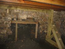
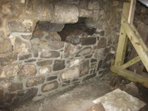
![Michael Fulp House, collapsed wall partly mudded-in"[gray mortar], #266](https://s3.amazonaws.com/pastperfectonline/images/museum_296/003/thumbs/100501057-3.jpg)
Additional Images [12]
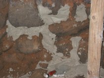
![Early local red-clay based mortar residue with [white] lime (#920, 11/13/10](https://s3.amazonaws.com/pastperfectonline/images/museum_296/003/thumbs/100501057-8.jpg)
![[#2873, 4/7/11]: Disintegrated mortar removed from wall during dismantling](https://s3.amazonaws.com/pastperfectonline/images/museum_296/003/thumbs/100501057-9.jpg)
![[#2875, 4/7/11]: Disintegrated mortar residue removed from wall, detail](https://s3.amazonaws.com/pastperfectonline/images/museum_296/003/thumbs/100501057-10.jpg)
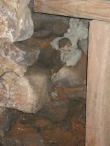
![[#2863, 4/7/11]: Disintegrated mortar residue in wall core](https://s3.amazonaws.com/pastperfectonline/images/museum_296/003/thumbs/100501057-11.jpg)
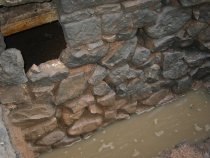
![[#669, 7/3/09]: shored cellar wall segment, soil & wall-stones on floor](https://s3.amazonaws.com/pastperfectonline/images/museum_296/003/thumbs/100501057-12.jpg)
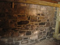
![[#1883, 4/7/11]:South gable wall](https://s3.amazonaws.com/pastperfectonline/images/museum_296/003/thumbs/100501057-17.jpg)
![[#2882, 4/7/11]: Dismantled exterior wall w/ small stone agregate in mortar](https://s3.amazonaws.com/pastperfectonline/images/museum_296/003/thumbs/100501057-13.jpg)
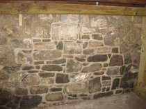
![[#1158, 10/7/10]: Scratch-coat pargeting on W segment of N gable foundation](https://s3.amazonaws.com/pastperfectonline/images/museum_296/003/thumbs/100501057-14.jpg)
![[#1238, 10/11/10]: E range of N gable foundation, prepping for dep-pointing](https://s3.amazonaws.com/pastperfectonline/images/museum_296/003/thumbs/100501057-15.jpg)
![[#1241, 10/11/10]: W portion of N gable wall, prepared for deep-pointing](https://s3.amazonaws.com/pastperfectonline/images/museum_296/003/thumbs/100501057-16.jpg)
Metadata
Collection |
Michael Fulp House |
Title |
18 photos of foundation and cellar wall restoration |
Archive Number |
MFHPH53 |
Description |
Series of 18 digital photographs depicting the September-October, 2010 reconstruction of the collapsed interior segment of the north gable foundation of the Michael Fulp [formerly "Bridge Keeper's"] House. This project also included the stabilization of the projecting exterior plinth in the sub-grade ranges forming the entire perimeter of the building. By 2008, after 225 years of exposure to numerous floods, soaking rain events, and absorbed snow-melts, augmented by a modest contribution from roof and ground run-off, the early lime mortar applied in the beds and joints throughout the foundation walling had become disintegrated and brittle ["friable"]. The relentless soak-freeze-thaw cycles caused the incremental dissolution of the lime binder from the mortar, producing an incoherent residue of sandy clay and coarse gravel rubble in the beds and joints between stone "units" of the walls [see photo #920 in this series, 11/13/10, and 4/7/11 photos #2873 & #2875 ]. Such residual material [see Image #920 and photo #2863, 4/7/11] provided a marginal bearing and bonding medium rather than establishing a stable and virtually "monolithic" integration of the foundation walls. Compromised mortar fails in the important function of distributing loads evenly throughout the wall. This function is an essential prerequisite to structural equilibrium and monolithic integrity in a masonry structure. Lacking a sound matrix of well-bondED mortar, stone walling depends on the tenuous stability afforded by its existing "in compression", a state "bound" only by gravity and lacking a binder between stones. This condition is barely more stable than a mortar-less ["dry-laid" or "stacked-stone"] wall, which survives only when all loads are borne in compression. The inevitable result from these incursions and their decomposing effects was the lateral and rotational displacement of foundation stones, allowing the injection of a muddy slurry and dislodged stones through the rubble core of the wall, propelled by hydrostatic(a) thrust into the cellar [see Image #669, 7/3/09]. By early 2009 the interior cavity created by the dislodged foundation materials extended 12-15 inches inside the interior plane of the wall [more than half its transverse width], and measured about 5 feet square in elevation. This gaping void had the appearance of a roughly delineated "fireplace" [photo #908]. (a) Technically, the movement of fluids under pressure becomes "hydraulic," usually operating in a closed system but roughly analogous here. The energy in the fluid current transports solids in its path until the lateral pressure is dissipated, which occurred in this situation when the foundation stones, "mortar" residue, and muddy slurry are thrust onto the cellar floor. All that remained standing of this wall segment was the exterior layer ["wythe"] of stones, containing little mortar of any significant bearing value [see image #236 , which shows the essentially mortar-less exterior facing, and photo #920 cited above]. Compounding the progressive degradation of this wall, and the impending catastrophic failure prevented by the shoring seen in photo #608, was the failure to deploy adequate "bond-stones" in the early foundation, partly because of the single-excavation technique discussed later in this record(b). Bond stones should be set at right or oblique angles to the planes of the wall and should be deployed to tie wall wythes together through the core of the wall. (b) Although inadequately utilized in the base-range of the foundation [below exterior grade], a limited number of relatively large stones were "toothed" into the above-grade wall segment under the first floor window [see Images #2869 & 2880, 4/7/11]. However, the loose ["friable"] rubble-core material of the wall, not a true bonding or bearing agent, severely limited the effect of these stone "ties," as evidenced by the two laterally-radiating settlement fractures extending from the window sill extremities down to grade. "Quoins" in the corner piers, alternating in "stretcher-header" alignment, are classic (and ancient) examples of bond-stones, and in this building they are substantial in size and well deployed. However, the early builders apparently considered the thickness of the wall between corners to be sufficiently massive to ensure a stable structure, without systematically installing bond stones in wall ranges between corner piers. The critical mass, thickness, adequacy of footing, and bonding quality of a stone wall are essential components of compressive stability. Equally important is well-formulated mortar, compounded to bear the stone mass and timber loads, to provide a "shock-absorbing" medium between stones, and to allow moisture to evaporate out through the joints. To be an effective load-distributor and stress-attenuator, mortar must be fully "mudded-in", filling all beds, joints, and voids with a firm but resilient and marginally adhesive "padding" for the stone "units". Two indispensable attributes of "random rubble" masonry walling in stable compression are vertically aligned ["plumb"] wall wythes and structurally coherent central cores. A wall of variable thickness and an out-of-plumb alignment produces a diminished margin of error in fulfilling its load-bearing function in stable "compression." Such defects impede the effective transmission of the incumbent loads through the foundation masonry to the clay bearing-plane supporting the base-blocks of the building. A corollary of this principle explains the uniform settlement of the whole structure without significant displacement of stone units or de-stabilizing fractures in the mortar network of the walls. Such monolithic settlement apparently occurred in the cases of the federal-era additions to the George Douglass mansion and the White Horse Inn [see records GDHPH…. and WHT…] Although more critical in eaves walls, which must counteract and effectively neutralize roof loads and thrust, any masonry wall should be constructed to transmit its incumbent stresses, including its own mass, "to ground" by confining the forces acting within it to the wall core [in general, the vertical rubble masonry mass sandwiched between "wythes"]. To remain stable, this vertical force-path must be confined within the "central third" of the thickness of the wall. Rubble masonry walling was never designed to provide stability against oblique or shearing loads. Good mortar functions at a high mechanical level in bearing compressive forces, but offers little frictional or structural resistance to lateral or oblique thrusts and loads. Photo #1883, 12/17/10 shows the south gable wall of the Fulp house during re-construction. The mason deployed bond stones transverse to the run of the wall, and laid a densely packed rubble core. The purpose of analyzing the construction techniques and mortar failure in a building whose foundation walls had survived for over two centuries is not to question the skills or practical structural techniques of the early builders. Rather, the benefit of determining the factors leading to threatened, partial, or total failure is to ensure that appropriate structural principles and traditional craft methods are fused to produce a sound remediation plan and an effective and lasting stabilization program. The restoration and reconstruction efforts of preservationists and the craftsmen they employ adhere as closely as possible to the materials and methods of the early builders, allowing for the introduction of modern materials, such as metal ties deployed in the bed mortar and lag-screws securing window frames to the adjacent wall ranges, to provide an inconspicuous but redundant mechanical advantage designed to extend the structural life-expectancy of the restored building and its components. The unstable condition of the foundations under the Fulp house was due in part to the original construction method, which consisted of laying-up the wall stones directly onto the bearing soils from inside the cellar{p} excavation rather than from both sides of the wall. This method precluded any opportunity to establish a plumb and well-pointed exterior wall-plane. The outer segments of the foundation were built-up by pushing stones against the vertical soil-bank forming the perimeter of the excavation. Some stones protruded into the soil and others didn't extend to the bank, leaving others cantilevered and only partially supported. This method was more economical, saving excavation and back-fill time, but it also precluded the opportunity to fully apply mortar by "deep-pointing" the exterior joints and beds of the foundation [see photo #236, showing voids in the exterior segment of the foundation]. The result was a foundation with a very irregular exterior contour, lacking any semblance of a common plane or sound bearing core. It is only because of the solid footings provided by the thicker plinth of the foundation walls and the well-executed "quoin" corner piers that these elements of Michael Fulp's modest house survived intact for nearly 185 years. {p} this method was employed only in the southern half of the foundation, where the cellar cavity exists, but obviously not in the northern half of the house, where only a crawl space exists below the first floor. The mortar applied from the inside the cellar excavation to the core of the wall [by "deep-" or "back"-pointing] didn't reach the exterior voids in the wall as face-joint pointing would. This reduction in the mass of mortar in the wall system allows more water penetration and eventually is unable to resist the lateral movement of stones and soils driven into the cellar by hydrostatic pressure. See archive record MFR10PH3--1005.01.059 for photos and discussion of the protective measures applied to the exterior foundation masonry to block and discharge such infiltration, and record MFR10FN2--1005.01.058 regarding the drainage system installed to rapidly reduce the hydrostatic pressure acting against the wall from the tons of water and mud surrounding the building below grade. Part of the remediation of the progressively under-functioning masonry in this building included the insertion of smaller stones ["pins," "plugs," and "chinks"] in beds, joints, and voids which were too large to be filled by mortar alone. Well-formulated mortar is the ideal "padding" and load-distributor in a random-rubble masonry wall, but should not be relied on as the primary bearing material. This function is better served by stone "units," integrated by bond-stones skillfully deployed in laying-up the wall. A loose aggregation of smaller stones, not well chosen for their size, shape, and potential bearing contribution, transfers the incremental stresses in the structure to other segments, potentially subjecting those components to strains beyond their capacity. As an example, photo #2882, 4/7/11 shows a large aggregate of small stones bound together by mortar, but otherwise not integrated into the foundation. In the course of the current restoration project the outermost stonework of the entire foundation of the building has been stabilized and reinforced with stones inserted into voids where possible, and packed fully with mortar pointed flush to the undulating contours of the face-stones ["barn-dash" pointing], and pargeted. Although redundant so long as the wall is in compression, this additional bedding and pointing mortar [more than ten tons in the entire project] will provide a significant increment of structural stability for many decades. The full foundation restoration process consisted of: (1) dismantling and re-laying the unstable segments of the interior wall (2) bonding the reconstructed foundation with longer stones "toothed" transversely through the wall (3) packing carefully formulated mortar and small stone into all joints and voids ("deep-pointing" and "back-pointing") (4) re-pointing the exterior wythe from an exterior excavation to provide a "flush" pointed contour to receive the mortar pargeting coat; (5) pargeting the exterior sub-grade exterior surface with the same mix as the bed mortar{2} [see photo #1158, 10/7/09 showing a "scratch coat"(n) of mortar on a portion of the repaired stonework; the balance of the rebuilt sub-grade foundation will be similarly pargeted, followed by (6) a "finish coat" of mortar of varying thickness to produce a contoured wall-plane more closely approximating a "plumb" alignment. (n) incised ["scratched"] with the trowel point to create "keys" which will be filled in with the finish pargeting, or plaster, to bond the two rendered applications together. This wall reconstruction process was followed by the application of two coats of a "green" water-based, rubberized liquid waterproofing ["Eco-Flex"] and a flexible "dimpled" drain board sheet material ["Delta Drain"] covered by an adhering high-grade "geo-textile" filter fabric. The latter two materials serve a more critical function than merely providing a moisture barrier. The drainage plane between the fabric and the impervious sheet material against the parge-coat allows some of the water absorbed in the soil to filter more quickly downward through the fabric fibers and open spaces between the drain board "dimples." This released water percolates into the stone drainage bed, is collected in the perforated piping and then discharged to a remote outlet through a solid pipe. This system dissipates a significant component of the hydrostatic pressure acting on the foundation, reducing both the magnitude of the lateral force and the volume of water attacking the foundation mortar and stonework and drains the foundation perimeter exponentially faster than natural percolation through the top-soil(c). These two significant benefits will substantially decelerate the relentless process which has degraded, and ultimately destabilized, this foundation for decades. (c) After the minor flood [river rose to second step of this building and flooded its cellar to a depth of about 18 inches] of March, 2011, and again in the flood of September, 2011 which reached the top of the Fulp window openings, several thousand gallons of ground water were drained away from the foundation through this system within a few days after the flood-crest. The portions of the sub-grade foundation flanking the central range remained marginally more stable, partly because of the buttressing and tying effect of the quoin corner piers and intersecting eaves wall foundations [see photos #1238 & #1241, 10/11/10, which show the slightly displaced but relatively stable east and west ranges of the foundation of the north gable wall]. Although relatively stable, the foundation segments flanking the rebuilt central section and extending to the corners were reinforced by raking out the loose mortar joints, packing mortar into the beds between stones ["deep-pointing"], and re-pointing the exterior joints. This "deep-pointing" process was followed by application of the "cementitious" pargeting material specified on the project engineering drawings [see MFR10DWG1--1005.01.055]. The "rendered" layers will then be covered with the drain board and fabric as described above. These foundations had survived for over two centuries because of the massive dimensions of the masonry wall system and a high quality local inventory of fieldstone highly suited to durable "rubble" construction(p). Nevertheless the walls were in peril of a catastrophic event as the more unstable segments began disintegrating. The 2010 restoration substantially reduced the risk of such an event. See archive record MFR10PH3--1005.01.059 for further discussion of the restoration of various foundation segments. (p) The stone types in the building will be listed in this record when the geological analysis is completed. FOOTNOTES {1} This building manifests both the effectiveness of this type of masonry and its deficiencies when imperfectly executed, as is apparent in the lack of "bond-stones" and deficient mortaring, both of which components are critical to creating a structurally sound and durable masonry wall. {2} On the advice of the project engineer the ratio of aggregate [primarily sand] to binders [cement and lime] was not less than 2 to 1, and not more than 3 to 1, thus neither too strong nor too weak, i.e. too hard or too soft. Hard mortar traps moisture in the beds and joints, subjecting the structure to damage from freezing and protracted dissolution of the mortar. See photo record MFR10PH4--1005.01.060 regarding the process of sampling and selecting mortar for function, texture, color, and compatibility with the stones composing the building. The mortar recipes used in this project consisted of sufficient water to "hydrate" the lime to the optimum consistency ["viscosity"], plus: A. For the restoration of cellar walls and foundations: 5 parts New Jersey "Yellow Bar" sand; 2 parts white lime; and ½ part gray Portland cement B. For above grade stonework beds and inner joints: 4 parts BP New Jersey Buff sand; 2 parts BP Masons White sand; 2 parts white lime; and 1 part gray Portland cement C. For pointing above-grade exterior joints: 4 parts BP Masons White sand; 2 parts BP New Jersey Buff sand; 3 parts white lime; and ½ part gray Portland cement. {3} In the original construction and periodic "restorations," most wall ranges were not "bonded" with larger stones keyed ["toothed"] through the core of the wall [the chimney and "quoin" corners are exceptions, indicating a conscious decisions to employ bond-stones only for specific "necessary" functions]. Further, many vertical mortar joints were set too close together, creating long potential failure-paths. These "fault-lines" would be impeded by more massive stones which would compress and "break" the otherwise uninterrupted series of joints susceptible to transmission of radiating fractures. Larry Ward |
Search Terms |
MFR10 MFHPH MFPH MFH Michael Fulp House Michael Fulp House Photo Wythe Bond Stone Hydrostatic Pressure Bed Mortar Pargeing BKR10PH Foundation Restoration Foundation Failure Foundation Drainage Scratch Coat Mortar Mix Drainage Board Waterproofing Deep Pointing Back-pointing Stone Pins |
People |
Michael Fulp |
Object Name |
Print, Photographic |
Accession number |
1005.01 |
Date |
2010 |
Photographer |
Ward, Laurence |
Catalog Number |
1005.01.057 |