

Archive Record
Images
Additional Images [4]
Metadata
Collection |
Mouns Jones |
Archive Number |
MJHTXT10 |
Title |
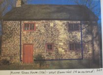
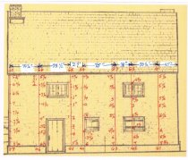
Mouns Jones House West Eaves Wall Restoration, 2014 |
Description |
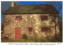
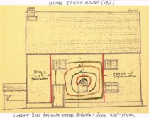
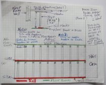
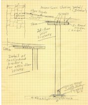
Mouns Jones House-Southwest eaves wall restoration outline-March, 2014 SUMMARY OF HISTORIC PROPERTY PLANNING DOCUMENTS: 1. Historic American Buildings Survey (HABS) documents in the Library of Congress: A. 1957: site plan, floor plan, elevations; B. 1958: 2 exterior photos; C. 1961: 4 data pages. 2. Wood engraved SW perspective view, showing re-located door and casement windows, as published in Montgomery, History of Berks County In Pennsylvania (1886) [see record# MJHDWG2]. 3. Scaled Plan and elevation drawings in Historic American Buildings Survey format by Barry K. Stover, 5-6-85, published in the Atlas of Architectural Drawings of Structures Preserved By The Historic Preservation Trust of Berks County, Pennsylvania (2008). 4. April, 1985 dimensioned Field Notes Drawings in pencil by Barry K. Stover-10 sheets, published in the Atlas of Architectural Drawings [Ibid.] (2008). 5. Numerous early- to mid-20th century photographs published in the Trust's on-line archives, showing earlier fenestration forms and approximate dimensions. 6. Copy of 1719 County Survey Draught of extension of "Oaley" Road, verifying location of Mouns Jones House on bank of Schuylkill River [see record# MVFN01]. 7. Elevation photographs showing masonry delineations of original doorway. 8. Structural load calculations and engineered drawings of shoring structures. 9. Dimensioned elevation drawings locating and delineating existing and restored doorway and fenestration elements [see attached elevation drawing showing existing and earlier fenestration openings and doorways. In addition to the openings shown, there was a temporary vertically aligned hung-sash window above the existing doorway, installed and removed during the 1965-70 restoration program]. 10. Computer-generated three dimensional renderings of deformed and misaligned segments of west eaves wall, from grid-based deviation calculations. 11. Photographs and elevation drawings documenting locations of numbered stone units prior to removal. SPECIFIC PROJECT DESCRIPTION: The planned restoration work on the west eaves wall of the 1716 Mouns Jones house is critical to stabilizing and re-aligning a structurally compromised wall section extending from the eaves to the foundation, and to restore the existing out-of-period 19th-20th century doorway and fenestration to their 1716 symmetrical configuration. (a) UNSTABLE STRUCTURAL CONDITION: Physical evidence, including plaster residue on floor joists and gaps between the cope-sawn floor board and the masonry surface, confirm the apparent lateral deformation of the walling in an area approximating 250 square feet. The misalignment of the rafter plates and the shift in wall-mass to a distended alignment cumulatively constitute an unacceptable risk requiring remediation. (b) RESTORATION OF ORIGINAL DOOR AND FENESTRATION PATTERN: The interior of the wall depicts vertical masonry joints of doorway dimensions and centered under the original 1716 date-stone sited in the second story wall range. The rediscovered vertical alignment between the date-stone and the original doorway location is consistent with the Anglo-Pennsylvania two and one-half story, single-pile, hall-parlor residence type often owned and/or built by Quakers in the expanding Philadelphia County area of influence [in some contexts called "The Philadelphia Trading Area"]. Although built for a second-generation Pennsylvania-Swede, the Mouns Jones house is an early and important "back-country" example of this transitional plan-form with its characteristic symmetrical three-bay principal elevation. WORK SEQUENCE: I.DOCUMENT EXISTING CONDITIONS AND MATERIALS: A.Photograph, plot, measure, number, and map existing locations of all stone units, door and window openings, embedded joist-leveling plate, and date-stone within the compromised two-story wall area [See attached drawings of shoring alignment and details: Images #7 and #8 These interior posts ["dead shores"] will not provide support for the roof load during restoration because the attic-floor joists supported by these shimmed posts do not extend to compressive support positions beneath the rafter plates [see Image #...attached, a sectional view showing the vertical miss-alignment of the joists and rafter plate]. B.Measure, plot, and record deformation of compromised wall ranges and its deviation from vertical planes of stable wall areas. C.Measure, plot, and record delineations of all existing and planned openings relative to fixed data points. D. Collect, log, store, and analyze samples of mortar from documented locations within wall area specified for removal, including mortar from all original and later-period masonry segments. II.Shoring: A. Install interior dead shores under each floor-joist [completed January, 2013 as a safety precaution], with cantilevered headers and laminated sills. B. Exterior shoring to be (1) supportive of all roof and floor loads presently borne by unstable wall segments, and (2) resistant to lateral and oblique thrusts. Shoring timber members shall be sized for redundant stabilization of all load and thrust vectors and all joints to be secured in accordance with consulting Professional Engineer's plans and specifications. III.Dismantling and demolition: A. Remove and store for sequential retrieval all stone units from wall-ranges within the project area. Replacement masonry to be woven in and bonded according to rubble pattern established by documented original walling B. Remove, document, and discard late-period windows and door, including framing. C. Remove, document, and preserve surviving original and early-period window sash and related framing. IV. Restoration: A. Inspect and stabilize foundation as necessary. B. (1) Re-lay stone units from segments of exterior wythe in original positions to the greatest extent possible within structural constraints and ascertainable early wall-pattern; (2) re-construct wall-core with adequate bond-stones aligned on transverse axis; (3) re-establish interior wythe as closely to original unit locations as is practicable. (4) Mortar for beds, joints, and pointing to be traditional 18th century lime-sand formulation based on results of analysis of mortar from early walling. C. Consolidate, re-level, and align structurally functional segments of 1716 joist plate above first-floor openings. D. Consolidate or replace deteriorated or structurally compromised floor joists. E. Fabricate and install four casement window sash and framing, using forms and proportions as documented elsewhere in house, in general form and configuration of surviving elements in east elevation, arranged with reference to vertical axis of re-centered doorway and date-stone. F. Fabricate period-style door and framing; install at original central location in wall range, aligned according to dimensions determined from photographs and measured drawings. QUALIFICATIONS OF KEY PERSONNEL/CONSULTANTS: The project will be designed, coordinated, and supervised by experienced volunteers in consultation with compensated professional consultants. The resumes of the Project Director, Laurence Ward, and the principal restoration consultant, Tom Lainhoff, are on-file. A professional engineer with extensive experience in designing timber structures will be engaged to perform load and thrust calculations, to design shoring necessary to support roof, framing, and floor loads during reconstruction of the masonry wall, and for consultation as necessary throughout the course of the project{n}. All design elements and restoration methods, materials, and practices will be in compliance with the Secretary of the Interior's Standards for the Treatment of Historic Properties. {n} Subsequently, TimberTech Engineering of Denver, PA was engaged to provide drawings [see record #MJHDWG3 in this archive] for the shoring specifications and detail drawings, and oversight for its construction. PUBLIC/COMMUNITY BENEFIT: After completion of the planned 2014 stabilization and restoration project, the Mouns Jones House and grounds will be open to the public on at least 100 days per year. Events and programs on scheduled dates will include interactive archaeological demonstrations, hearth-cooking and other 18th century instructive food-ways and heritage gardening programs, presentations on early construction craftsmanship and other architectural and historical subjects, and interpretive tours of the house and its Morlatton Village setting. Trust volunteers will be at the site during all open-hours. Specific programs and events, and all changes to the schedule of open-hours, will be posted on the Trust's website. |
Date |
2014 March |
Object Name |
Field Notes |
Catalog Number |
1000.01.119 |
Search Terms |
Wall restoration MJHTXT |
Notes |
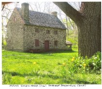
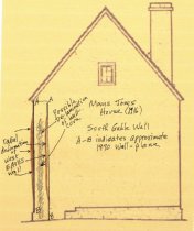
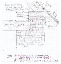
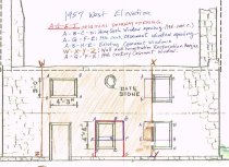
Notes: *Complete Image Captions: Image #1 - Deformed river-side [west] wall before restoration; doorway and fenestration are in 19th-20th century configuration. Image #2 - MJH SE perspective: East eaves wall with centered doorway. Image #3 - MJH Deformation contours: "Bulls-eye" contour lines showing radial-average displacement from wall plane in inches. Image #4 - MJH SGW profile: South Gable wall elevation sketch showing curvature of distended west eaves wall. Image #5 - Elevation photo with blue-line delineating distended wall area to be dismantled and re-constructed in bonded-rubble masonry technique; Image #6 - Wall Plane drawing with in-plane gauge-boards measuring varying wall displacement in inches. Image #7: Interior shoring drawing showing support of floor loads during wall reconstruction. Image #8: Detail drawing of interior shoring posts and headers supporting floor joists during wall reconstruction. Image #9: Mouns Jones House typical detail of rafter engaged with 2-plank rafter [bearing] plate, with attic floor joist borne in wall-pocket. Image #10: Field-Notes drawing of varying fenestration configurations within west eaves wall area to be re-constructed. |